Building OSPF Network
Sat, Feb 3, 2018Introduction
NOTE: all files can be found here
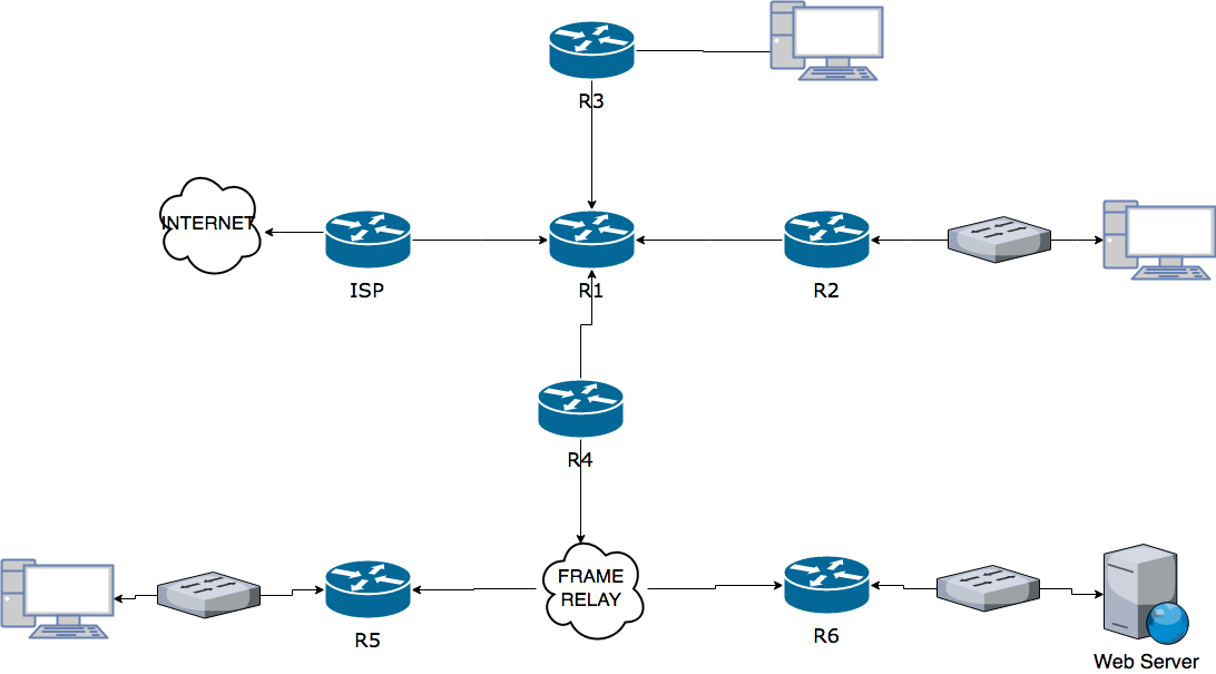
This post will detail the configuration of a multi network topology that is shown below. This topology incudes multiple subnets and Frame Relay.
For this post I will be creating a topology with the following requirements:
- All routers will be configured with appropriate hostnames and MOTD banners. DNS lookup should be disabled and messages prevented from interrupting CLI input.
All routers will be secured with passwords, AAA authentication and all unused network services will be disabled.
I will use one public class C license (202.100.37.0/24). This is not sufficient for complete internal addressing so the internal network will use the private address block 10.111.0.0/8.
The WAN connection to the ISP will be on the IP network 196.1.1.40⁄30. The ISP’s will also have a loopback interface and this interface will use an IP address of 126.0.0.1⁄8 to simulate the Internet connection.
Using VLSM I will add the following number of hosts and LANs on the following routers.
204 hosts on the LAN at R2
50 hosts on the LAN at R3
7 LANs, each with 44 hosts at R5, I will implement 1 LAN and simulate the rest with Loopback interfaces.
6 LANs, each with 44 hosts at R6, again I will implement 1 LAN and simulate the rest with Loopback interfaces.
I will make all subnets as small as possible and assign the first useable IP address to the router interface and the last useable IP address to the host device if required.
I will configure NAT on R1 to translate between private and public IPs. The web server hosts the web business and therefore must have a fixed address assignment.
I will use OSPF as the routing protocol. The connection to the ISP will not be included in these advertisements and I will not advertise routing updates out of the Ethernet interfaces of any router.
A default route to the ISP will be added on R1 and I will configure this to propagate through the network via the routing advertisements. A static route from the ISP to the network will also be added.
DHCP will be configured on R3 to automatically assign IP’s to hosts on the LAN.
The serial connection between R1 and R2 will use PPP with CHAP authentication.
A hub and spoke Frame Relay topology will be configured, with R4 acting as the hub and R5 and R6 acting as spokes.
ACLs will be configured so users in the LAN attached to R2 are only allowed web access to the Internet and users in the LAN attached to R3 are not permitted to access the web server connected to R6.
Design Phase.
Network and Interface Design.
To begin with designing the network, I examined the no of hosts and worked out the number of separate networks I would need.
It will require:
6 * /30 networks for the serial connections on the routers.
6 * /24 networks for the networks on R6.
7 * /26 networks for the networks on R5.
1 * /24 networks for the network on R2.
1 * /26 network for the network on R1.
In total that came to 7 * /24 networks and 8 */26 networks.
For these /30 connections, one connection would have to be to the ISP so that would be on the same network as the ISP. As the ISP network was given in the assignment brief, I determined that the serial connection on R1 to the ISP would be in the 196.1.1.40⁄30 range. Only two useable IP’s are available in this range. I decided on 196.1.1.41 for the ISP and 196.1.1.41 for the serial connection on R1.
With the other 5 * /30 networks I had decided to use the first useable range in the network I was given. So the network used for the Point-to-point connections would be 10.111.0.0 /30, 10.111.0.4 /30 network and so on.
Next, I decided to start with the biggest networks which were the 6 * /24 on R6. I gave these networks the next available networks in my slected internal network range. So the addresses of the 6 * /24 networks are as follows: 10.111.1.0 /24, 10.111.2.0 /24, 10.111.3.0 /24, 10.111.4.0 /24, 10.111.5.0 /24 and 10.111.6.0 /24.
Since I will use multi area OSPF, I wanted to keep the 7 * /26 networks on R5 and 6 * /24 on R6 in the same range so I could summarise these networks for smaller OSPF tables and for quicker lookup. These networks have the network address: 10.111.7.0 /26, 10.111.7.64 /26, 10.111.7.128 /26, 10.111.7.192 /26, 10.111.8.0 /26, 10.111.8.64 /26 and 10.111.8.128 /26.
The networks left are 1 * /24 network on R2 and 1 * /26 on R3. I will assign the larger of the two first, so the 1 * /24 network will be assigned the next free network in my range which is
10.111.9.0 /24. The smaller network I will assign 10.111.10.0 /26.
IP Subnet workings.
The network 10.111.0.0 / 16 converted to binary = 00001010 01101111 00000000 00000000
The subnet mask is 11111111 11111111 00000000 00000000 or 255.255.0.0
On R2 there is 204 hosts this means that it will be too small for a /25 network so I had to use a /24 network even though there will be about 50 unused IPs in the range.
The network on R2 converted to binary = 00001010 01101111 00001001 00000000and the subnet mask will be 11111111.11111111.11111111.00 000000 or 255.255.255.0.
R3 on the other hand will only have 50 hosts so I could use a /26 network, as it is too small for a /25 and too big for a /27. This network will have 12 unused IPs in the range.
The network on R3 converted to binary = 00001010 01101111 00001010 00000000 and the subnet mask will be 11111111.11111111.11111111.11 000000 or 255.255.255.192.
Furthermore, R5 will have 7 networks of 44 hosts. These 7 networks will all be /26. The networks in binary are as follows:
10.111.7.0/26 00001010 01101111 00000111 00000000
10.111.7.64⁄26 00001010 01101111 00000111 01000000
10.111.7.128⁄26 00001010 01101111 00000111 10000000
10.111.7.192⁄26 00001010 01101111 00000111 11000000
10.111.8.0/26 00001010 01101111 00001000 00000000
10.111.8.64⁄26 00001010 01101111 00001000 01000000
10.111.8.128⁄26 00001010 01101111 00001000 10000000
Finally, R6 will have 6 networks of 210 hosts. These 6 networks will all be /24. The networks in binary are as follows:
10.111.1.0 00001010 01101111 00000001 00000000
10.111.2.0 00001010 01101111 00000010 00000000
10.111.3.0 00001010 01101111 00000011 00000000
10.111.4.0 00001010 01101111 00000100 00000000
10.111.5.0 00001010 01101111 00000101 00000000
10.111.6.0 00001010 01101111 00000110 00000000
All of the networks on R2 and R3 can be summarised as /21 since all the networks on have the same first 21 bits when converted to binary.
I used the same process to summarise all other network areas for OSPF.
Host Design.
For PC-A in the 10.111.10.0 /26 network connected to R3, I will be assigning this a temporary IP address as outlined in the brief DHCP will be enabled on R3. The reason I will be assigning this a temporary IP is for testing the network before I implement DHCP.
The host addressing is as follows:
PC-C in the 10.111.7.0 /26 network connected to R5 will be assigned 10.111.7.62
Web Server in the 10.111.1.0 /24 network connected to R6 will be assigned 10.111.1.253
PC-B in the 10.111.9.0 /24 network connected to R2 will be assigned 10.111.9.253
PC-A in the 10.111.10.0 /26 network connected to R3 will be assigned 10.111.10.62
Security.
I will secured all routers by using the “username secret” command as this command encrypts a user’s password with MD5 hashing. Having a username also adds extra protection as the attack must not only have the password, but needs the username to get access to the device.
The username I configured on all of my devices is “alan” and the password is “kelly”.
Furthermore, I configured AAA authentication. I was going to configure the device to lock out a user if the password entered was incorrect, but the command would not work on packet tracer. After doing some research online, I found out that this feature is not available in packet tracer. On a physical machine, a user can configure this using the “aaa local authentication attempts max-fail <max-attempts>” command.
Just to add an extra bit of protection, I decided to disable “vty” except for SSH as some “vty” connections can send passwords and usernames in plain text(see here), so they are not very secure. SSH does not have this problem and is a very secure way to remotely control your device. To do this, I used the following commands “line vty 0 15” and “transport input ssh”. Furthermore, I configured all devices to use SSHv2, as it improves a lot of the weakness that could be found in SSHv1. Also I set up an ACL so that only computers in the network can access the routers via SSH. In a real life scenario, I would allow only the network admin computer access to the routers instead of all the network.
Building on the other security measures I enabled on the device, I decided to disable the Cisco discovery protocol (CDP). The reason for this is that CDP is a cisco protocol that can allow an attacker that has gained access to my network the ability to view Cisco devices the attacker could potentially exploit. This CDP can be very useful for trouble shooting but should be disabled after the network is configured.
Finally, one of the last features to improve security on the device was to disable the “aux” interface. I know that for this interface to be a security threat an attacker must first get access to the physical machine, but I decided for the sake of a few seconds I would disable the interface to limit the potential security risk.
OSPF
When designing the network, I decided to have four separate OSPF areas. The areas would be 0, 1, 2 and 3. In my backbone area 0, the routers would be R1, R2, R3 and R4. As these routers are all in the backbone, they are be called Backbone router(BR). R1 is also an Autonomous System Boundary Router (ASBR) as it is attached to an external network the ISP. The Area Border Routers(ABR) are: R2, R3 and R4.
Area 1 would consist of all the networks on R5 and on R6. Area 2 would contain just the single network on R2 and area 3 would contain the single network on R3.
I could do with area 2 and 3, but as this was my first network design and implemention I designed it for expansion. The single /24 network on R2 could be split up and on R3 I could add many more networks, as my address range is still nowhere near depleted.
As all the routers are connected using serial(point2point), so there will be no DR, BDR, etc.… election here. I will be leaving all hello and dead timers at the default settings.
Furthermore, I made all loopbacks and Ethernet interfaces on each device passive so OSPF updates will not be sent out on these connections.
On R1 I can summarise the network area 0 to 10.111.0.0 /24.
On R2 I can summarise the network area 2 to 10.111.9.0 /24.
On R3 I can summarise the network area 3 to 10.111.10.0 /26.
On R4 I can summarise the network area 3 to 10.111.1.0 /21.
Summarising can greatly reduce the routing table and improve performance such as Reduced link-state update overhead and reduce the frequency of SPF calculations.
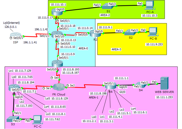
Topology Diagram
Addressing Table
| Device | Interface | IP Address | Subnet Mask | Default Gateway |
|---|---|---|---|---|
| ISP | Lo0 | 126.0.0.1 | 255.0.0.0 | N/A |
| S0/0/1 | 196.1.1.41 | 255.255.255.252 | N/A | |
| R1 | S0/0/0 | 10.111.0.10 | 255.255.255.252 | N/A |
| S0/0/1 | 10.111.0.18 | 255.255.255.252 | N/A | |
| S0/1/0 | 10.111.0.13 | 255.255.255.252 | N/A | |
| S0/1/1 | 196.1.1.42 | 255.255.255.252 | N/A | |
| R2 | G0/0 | 10.111.9.1 | 255.255.255.0 | |
| S0/0/0 | 10.111.0.14 | 255.255.255.252 | ||
| R3 | G0/0 | 10.111.10.1 | 255.255.255.0 | |
| S0/0/1 | 10.111.0.17 | 255.255.255.252 | ||
| R4 | S0/0/0.1 | 10.111.8.193 | 255.255.255.252 | |
| S0/0/0.2 | 10.111.8.197 | 255.255.255.252 | ||
| S0/0/1 | 10.111.0.9 | 255.255.255.252 | ||
| R5 | G0/0 | 10.111.7.1 | 255.255.255.192 | |
| Lo0 | 10.111.7.65 | 255.255.255.192 | ||
| Lo1 | 10.111.7.129 | 255.255.255.192 | ||
| Lo2 | 10.111.7.193 | 255.255.255.192 | ||
| Lo3 | 10.111.8.1 | 255.255.255.192 | ||
| Lo4 | 10.111.8.65 | 255.255.255.192 | ||
| Lo5 | 10.111.8.129 | 255.255.255.192 | ||
| S0/0/1.1 | 10.111.8.194 | 255.255.255.252 | ||
| R6 | G0/0 | 10.111.1.1 | 255.255.255.0 | |
| Lo0 | 10.111.2.1 | 255.255.255.0 | ||
| Lo1 | 10.111.3.1 | 255.255.255.0 | ||
| Lo2 | 10.111.4.1 | 255.255.255.0 | ||
| Lo3 | 10.111.5.1 | 255.255.255.0 | ||
| Lo4 | 10.111.6.1 | 255.255.255.0 | ||
| S0/0/1.1 | 10.111.8.198 | 255.255.255.252 | ||
| Web Server | NIC | 10.111.1.253 | 255.255.255.0 | 10.111.1.1 |
| PC-A | NIC | 10.111.10.62* | 255.255.255.192 | 10.111.10.1 |
| PC-B | NIC | 10.111.9.253 | 255.255.255.0 | 10.111.9.1 |
| PC-C | NIC | 10.111.7.62 | 255.255.255.192 | 10.111.7.1 |
* Denotes address that will change after the implementation of DHCP on R3
Implementation Phase
Requirement 1
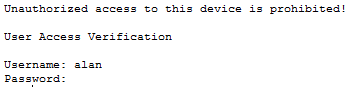
I assigned Router the hostnames outlined in the assignment brief. After careful consideration I decided to go with “Unauthorized access to this device is prohibited!” for the MOTD banner message. To disable domain lookup, I used the command “no IP domain-lookup”.
As there are many ways you can login into the router, for example console, telnet and SSH,
I decided to enable logging synchronous on all of these interfaces so the user would not be interrupted by message while entering CLI input.
Requirement 2
The way I verified that my configuration of my username and password were configured correctly was when I logged out of the device. When I tried to enter the device this time, I was prompted for a username and password as you can see below.
A screen shot of the authentication on one of the routers.
To verify AAA authentication was configured, I did a “*show run*” and I could confirm that it was configured.
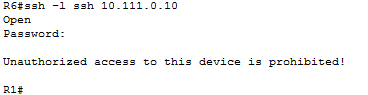
As for testing the functionality of SSH, I remotely logged into a router from another and was prompted with the password for the user I tried to log in as. Again, below you can see a screen shot of this.
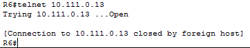
To confirm telnet was disabled, I attempted to log into devices using telnet and was prompted with the message below to verify that telnet was indeed disabled.
Requirement 3
I assigned the ISP and R1 the IP’s mentioned in requirement 3 in the assignment brief the IP’s I have in the addressing table. To test the IP’s were assigned correctly, I used the command “*show ip int brief*”
Requirement 4
I assigned all of the remaining networks the IP’s I have in the addressing table. I made all subnets as small as possible and assigned all clients the last IP in their network range.
Please see my Topology diagram for the IP addresses of devices.
Requirement 5
To configure NAT, I first assigned the web server a static web address on R1. I then set up dynamic NAT for all other devices in the network. After configuring NAT, I had to assign the interfaces that use NAT and the interfaces that do not use NAT. After this, any device will still not be able to ping the ISP as the ISP does not know where to the return the traffic. So the ISP could return the ICMP echos, I set up a static route from the ISP to R1. I go into this in more detail in requirement 7.
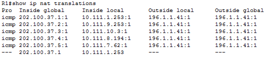
To verify NAT functionality, I used the command “*show ip nat trans*”
This showed the below table of all the external IP’s mapped to the internal private IP’s.
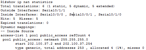
Furthermore, for more details on the NAT configuration, I used the command “*show ip nat statistics*”. This command shows how many translations are in the table and how many are static/dynamic. As you can see in the screenshot below, this command also shows the public address range of NAT, among many other NAT configurations.
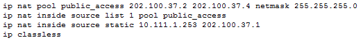
A screen shot of some of the commands entered in R1.
Problems Encountered
Problem 4
Requirement 6
After adding each network to the OSPF process, I tested were all the router neighbor adjacencies up. To test this, I used the command “*show ip ospf neighbor*”. After seeing that all neighbor adjacencies were up, I then tested the ability of the networks to communicate with other networks in the network. I also viewed the routing tables on each device to make sure that it had a route to each network. The command I use to view the routing tables was “*show IP route*”. After I was happy that all networks had routes in every router routing table, I then summarised each network area and proceeded to test the functionality of the networks to be able to communicate with each other again.
Problems Encountered
Problem 5
Requirement 7
To configure the default route to the ISP on R1, I used the command.
“*ip route 0.0.0.0 0.0.0.0 Serial0/1/1*”.
Furthermore, to propagate this route throughout the network, I used the following command.
“*default-information originate*”
Verification that the default route was propagated throughout the network below is part of R6 routing table.
![]()
For the static route from the ISP to R1, I used the command.
“ip route 202.100.37.0 255.255.255.0 Serial0/0/1”
Requirement 8
To verify that DHCP was functioning correctly, I changed the IP configuration on PC-A to receive its IP configuration via DHCP instead of being assigned statically. As you can see below, the device successfully received IP configuration from the DHCP.
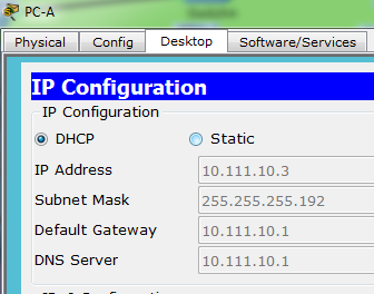
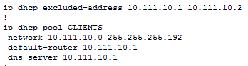
DHCP commands entered on R3
Problems Encountered
Problem 3
Requirement 9
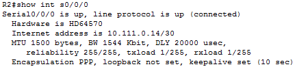
TO verify that I had configured the encapsulation to PPP I used the “show int” command
Verification that PPP encapsulation is used between R1 and R2.
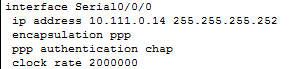
To verify that chap authentication was in use between the interfaces, I changed one of the interfaces to use PAP authentication and observed the interface going down and the router losing adjacencies with one another.
Interface commands enter to achieve chap authentication on R2
Requirement 10
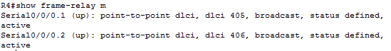
A Hub and spoke frame-relay design means that all traffic from the spokes must travel through the hub.
Verification that R4 is acting as the hub in a frame relay topology.
![]()

Problems Encountered
Problem 2
Requirement 11
To only allow any device on the network 10.111.9.0 /24 access to the internet, I used extended ACL to deny any device on the network access to the internal private network by creating the following access-lists. I also added an ACL to stop any device on the network to access the internal network by using it global addresses.
“access-list 101 deny ip 10.111.9.0 0.0.0.255 10.111.0.0 0.0.255.255”
“access-list 101 deny ip 10.111.9.0 0.0.0.255 202.100.37.0 0.0.0.255”
“access-list 101 permit ip any any”
To verify the functionality of the access control lists, I attempted to access the internal network. I used different methods depending on the device. I attempted to ping each device on the network using the device’s private IP address and their global IP addresses. When testing access to the webserver, I attempted to access it from a web browser along with trying to ping it.
Initially I did not have the command to deny access using the network’s global address range, but after testing other aspects of the network, it dawned on me that I had not fully denied access to the internal network. Therefore, I created a ACL implicitly denying it access to the networks global address range.
To deny any device on the network 10.111.10.0 /26 access to the Web Server, I again used extended ACL to achieve this.
The ACL I add are:
“access-list 100 deny ip 10.111.10.0 0.0.0.63 host 10.111.1.253”
“access-list 100 deny ip 10.111.10.0 0.0.0.63 host 202.100.37.1”
“access-list 100 permit ip any any”
As previously mentioned, I had not initially denied access to the Web Servers global address, but after testing other aspects of the network, it dawned on me that I had not fully denied access to the Web Server. Therefore, I created a ACL implicitly denying it access to the web servers global address.
Problems Encountered
Problem 1
Problems Encountered and Solutions
Problem 1(ACL Problem)
I encountered many issues while configuring the ACLs, such as repeatedly entering the commands in the incorrect order. Firstly, I had denied the network access to the network or device and added to permit everything else. Furthermore, when I found out that I must also deny the network access to the global address, I added that command, but I was still able to access the network or device via the global address. I then realised after a “show run” that I entered the commands in the wrong order and that the commands were evaluated on the order entered. I also encounter syntax issues. After encountering these issues, I believe I have a far greater knowledge of ACLs and I have my improved my ACL troubleshooting abilities.\
Solution
How I resolved the issue of repeatedly entering the commands in the incorrect order was that I read over my old notes and just deleted the ACL and started again in the correct order. Furthermore, I found IOS “?” and “help” commands very helpful and caused me to improve my ACL syntax knowledge greatly.
Problem 2(Frame-Relay)
I must say, for some reason, I found it difficult to understand the idea of hub and spoke. I read through my notes on frame relay but still found it difficult to understand the principle.
Solution
I spoke to my lecturer and after that the idea became very clear. Looking back, I found it hard to understand why I had such trouble understanding such a simple design. I think it must have been a Monday.
Problem 3(DHCP)
A very minor issue I encountered here was I entered the subnet mask of the network incorrectly and it caused PC-B not to be able to receive the IP configuration via DHCP.
Solution
I looked at the commands I entered and noticed I had entered a /24 subnet mask instead of a /26. I removed the command and entered the correct command and PC-B successfully received its IP configuration setting via DHCP.
Problem 4(NAT)
For some reason after setting up dynamic NAT, internet connectivity was intermittent.
Again, a very minor issue but something that took me awhile for me to recognise. I had mistakenly entered the incorrect address range, that was only allowed a few devices to access the internet at once.
Solution
Having used the show “ip nat statistics” command and having seen that I had entered the incorrect address range, I changed the address range to the correct address range and the connection to the ISP was no longer intermittent.
Problem 5(OSPF)
While trying to summarise the network in area 1 on router 4, I was prompted with an error message. I then realised I had missed that the serial interfaces would be out of the area address range. To rectify this, I had to change the networks that sub interfaces of serial 0/0/0 on router 4 were using as they were not part of the area to be summarised.
Solution
As I had the /26 network of the 10.111.8.192 free, I decided to use this for the serial interfaces. So, the IP’s of the serial interfaces on R4 were 10.111.8.193 and 10.111.8.197. This then allowed me to summaries my area 1 and required minimal modification of my network.
Config files and Packet Tracer file links
Routers and Switches running configs with comments
| R1 | R2 | R3 | R4 | R5 | R6 |
|---|---|---|---|---|---|
| ISP | S1 | S2 | S3 | S4 |